These pictures were takes as we built one of our test carts.
It is important to have the Middle plate oriented correctly. There are 3 sets
of two holes in the Middle plate used to screw down
the connectors. The 3 Outer
Walls have square holes above the cutout that should line up with these connector
locations. The edge of
the Middle Plate without these holes is the FRONT.
Most of the weight of the batteries is borne by the Bottom Plate where it is
attached to the Outer Wall. Be sure to use
nails, screws, and glue. Avoid nailing
into a board near its edge to prevent splitting
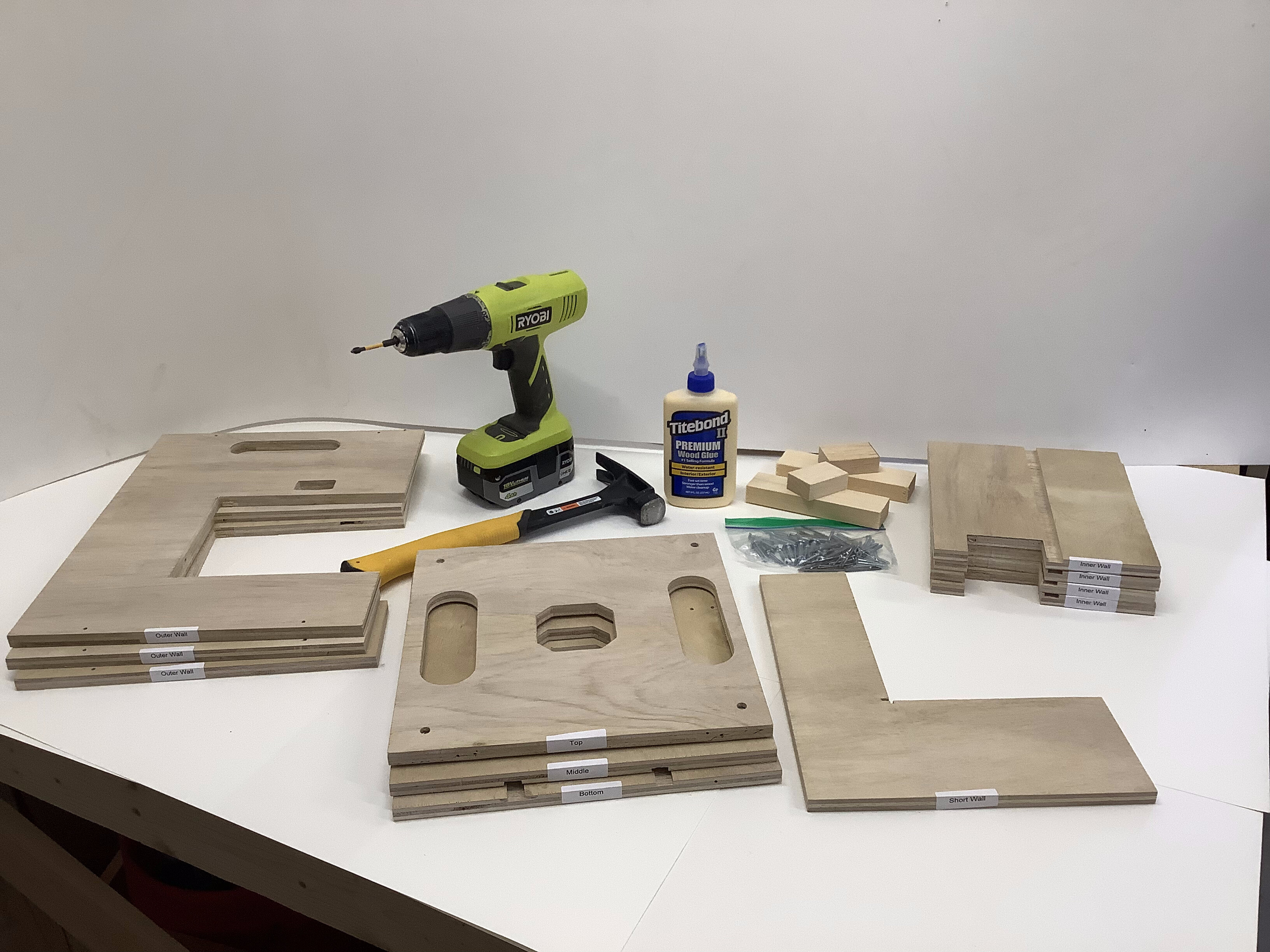 |
You should have all of these pieces. Check agains the Parts List. Left to right - 3 Outer Walls, 3 plates (Bottom, Middle, and Top), 1 Short Wall, and 4 Inner Walls, Mounts and a bag of Hardware. |
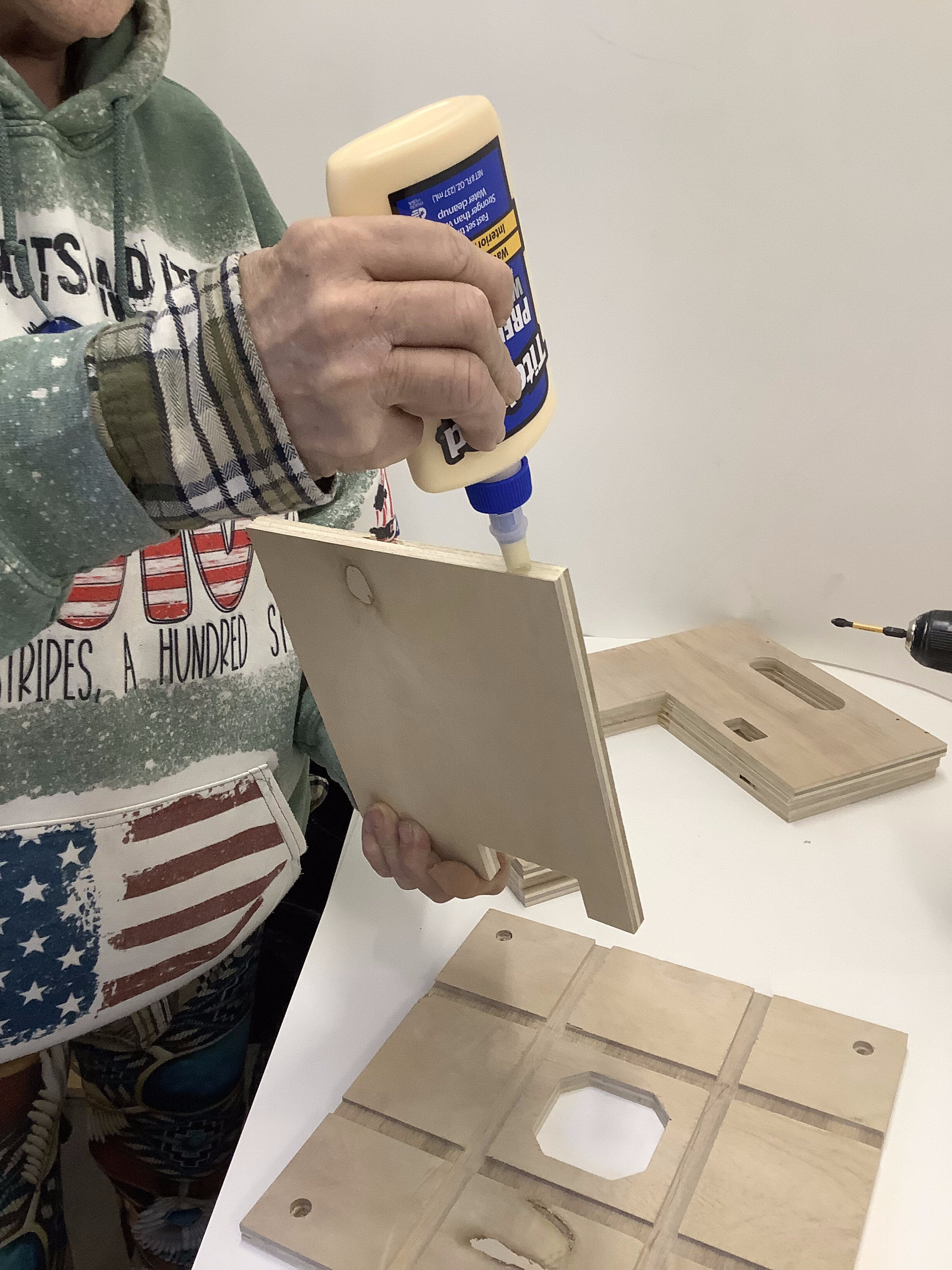 |
| Attach Inner Walls to Bottom Plate using plenty of glue on bottom and in groove. |
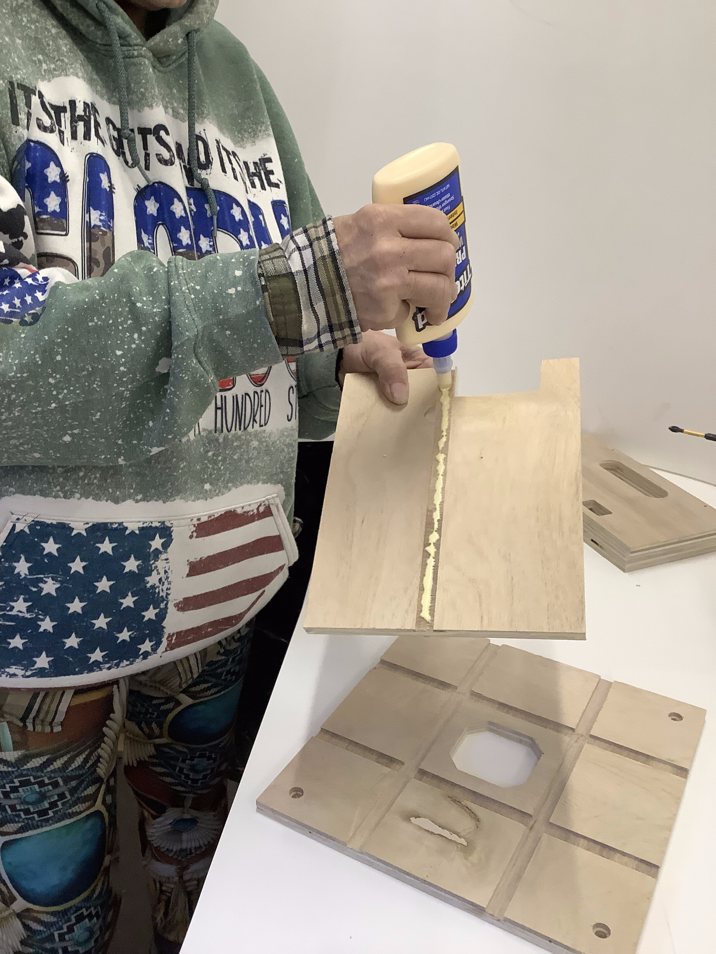 |
Really, use plenty of glue! |
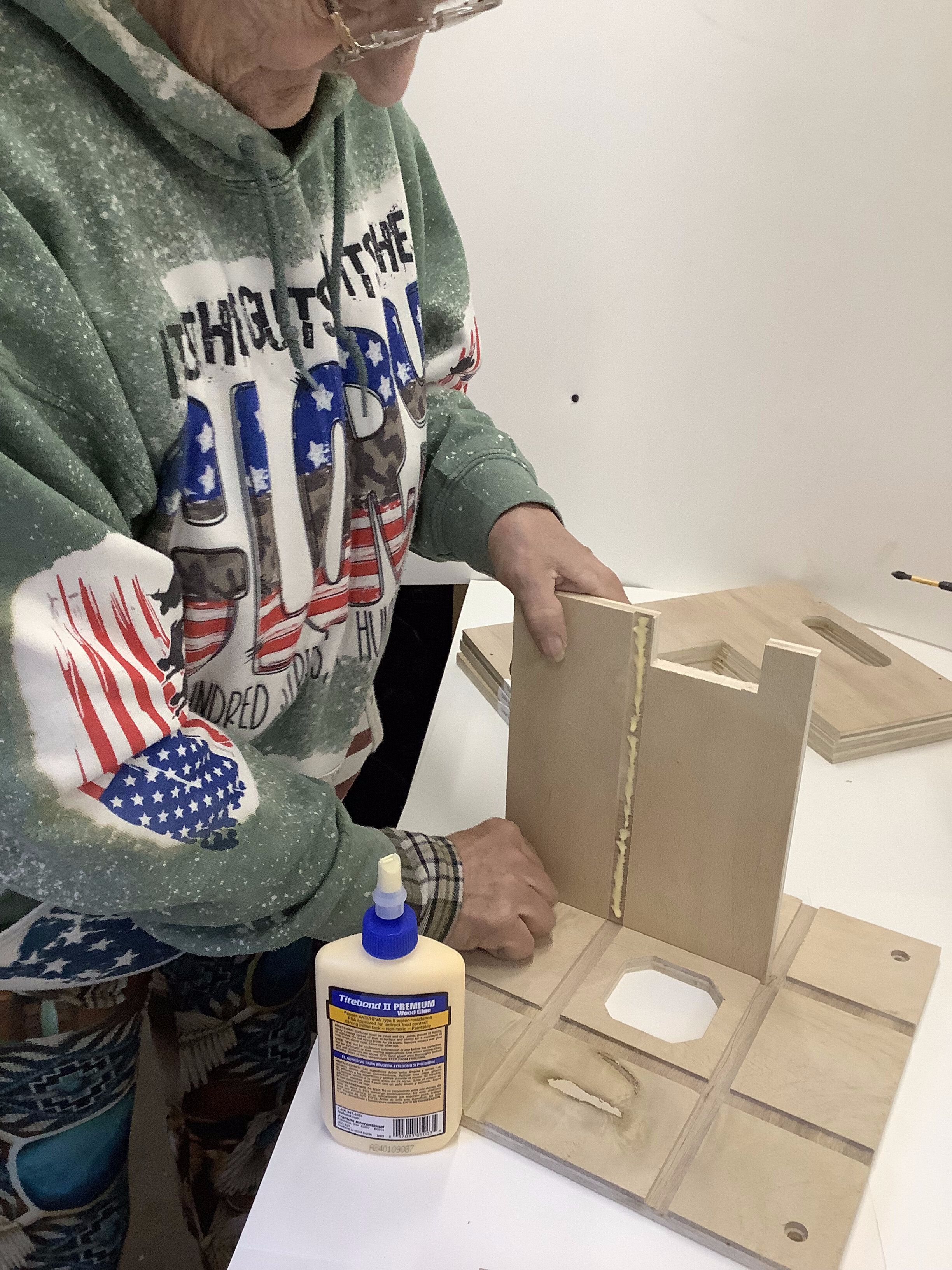 |
| Place an Inner Wall in a Bottom Plate groove as shown. The knotch should be towards the center. |
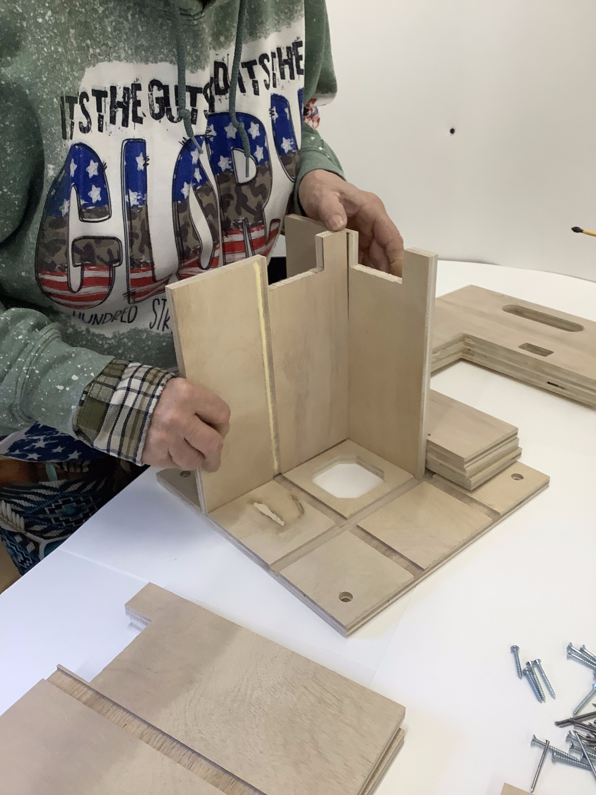 |
Glue and place the other 3 Inner Walls on the Bottom Plate. |
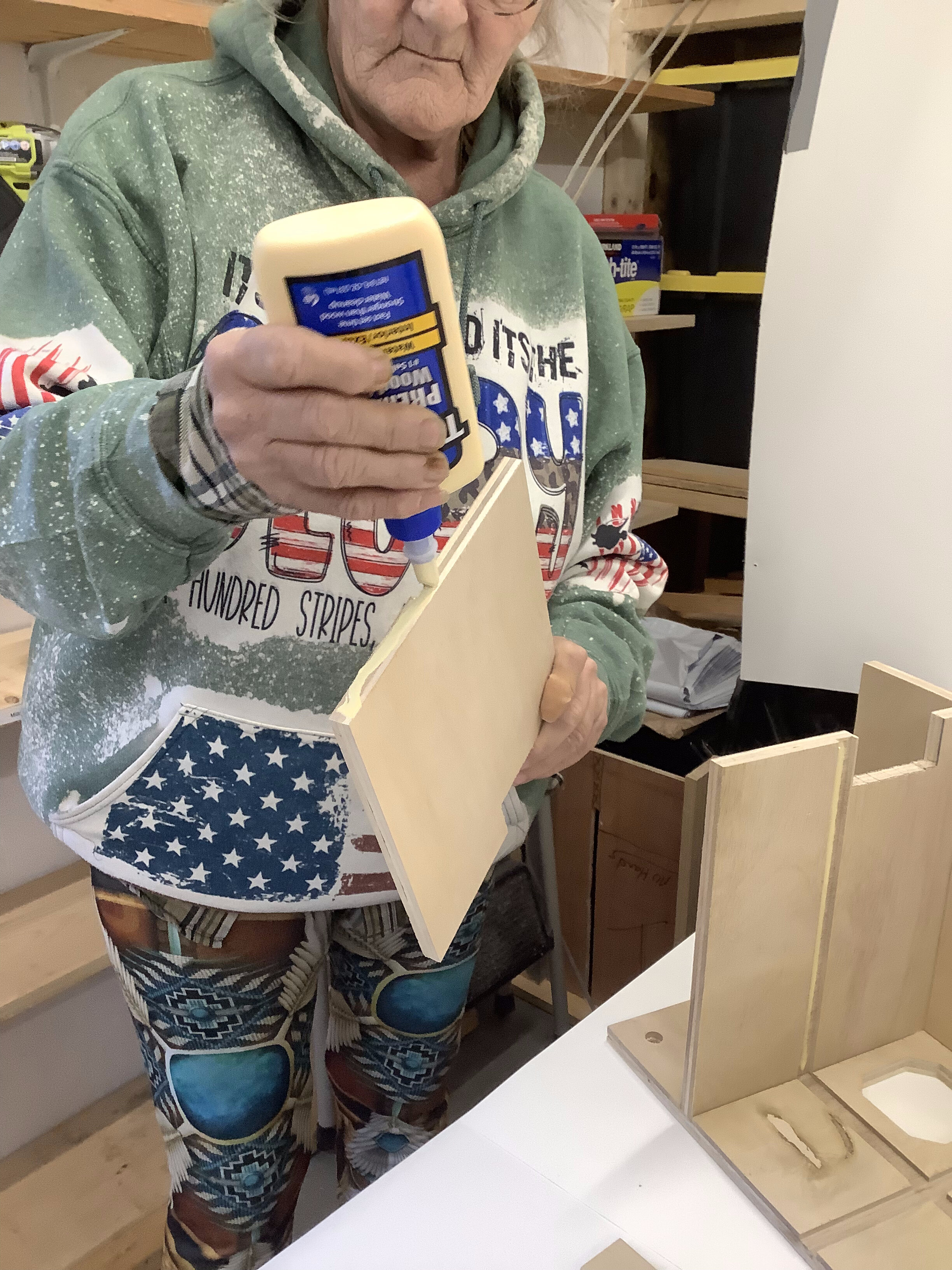 |
| Keep going! |
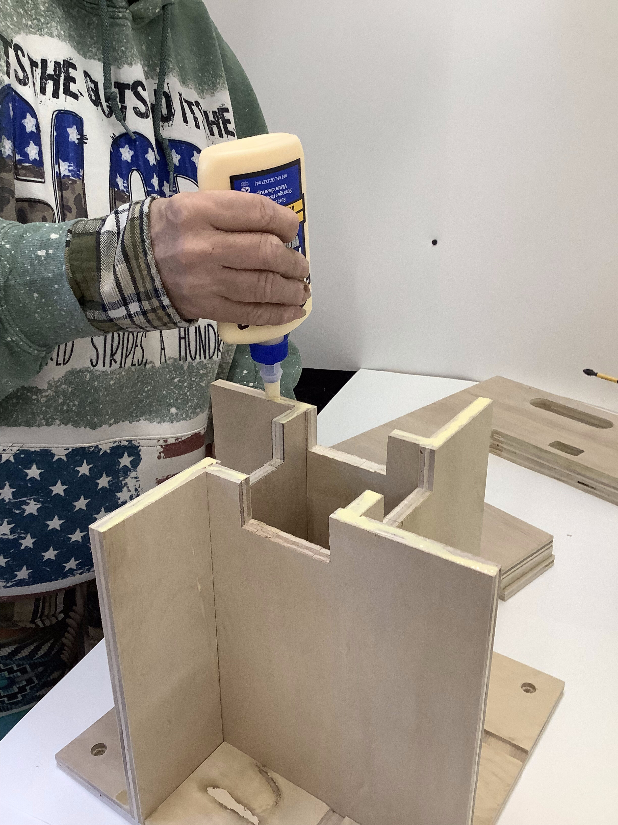 |
Glue the high points of the Inner Walls. |
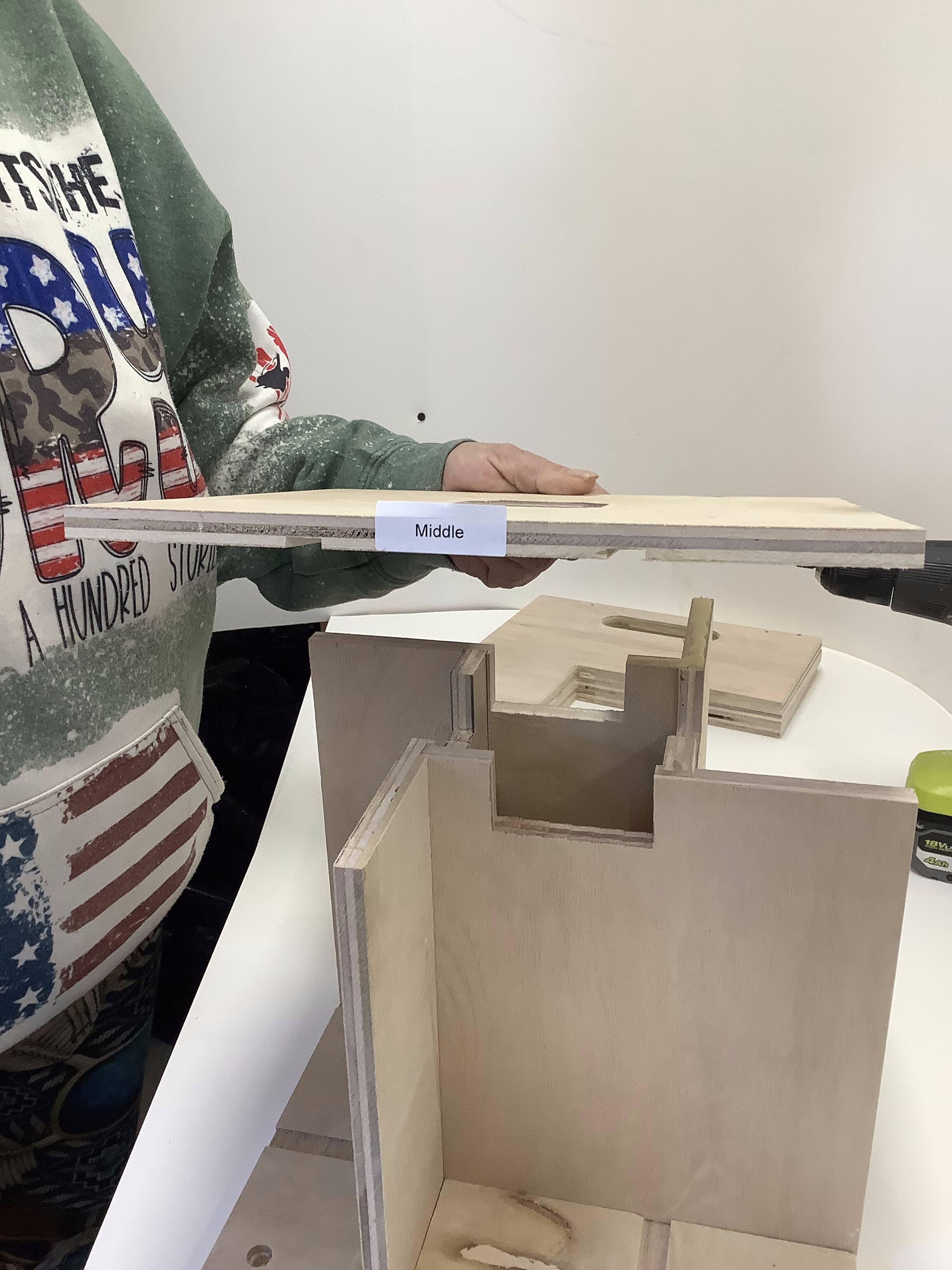 |
| The groves in the bottom of Middle plate will accept the glued tops of the Inner Walls. |
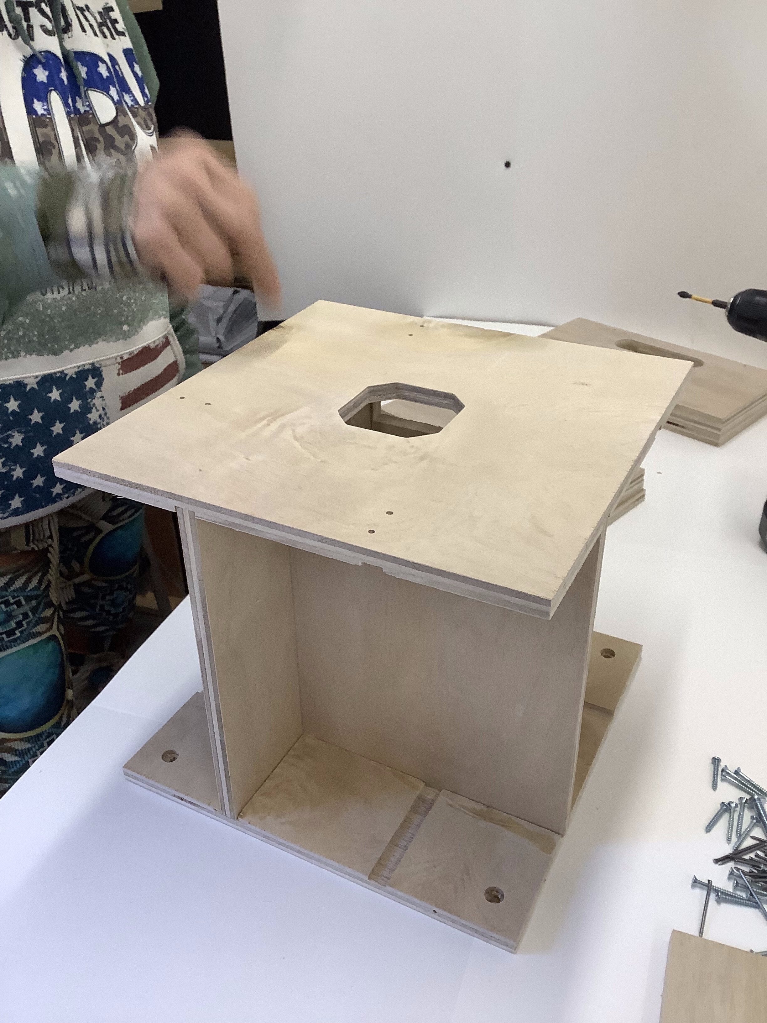 |
Double check that the Inner Walls set completely in the groves in the Middle Plate. |
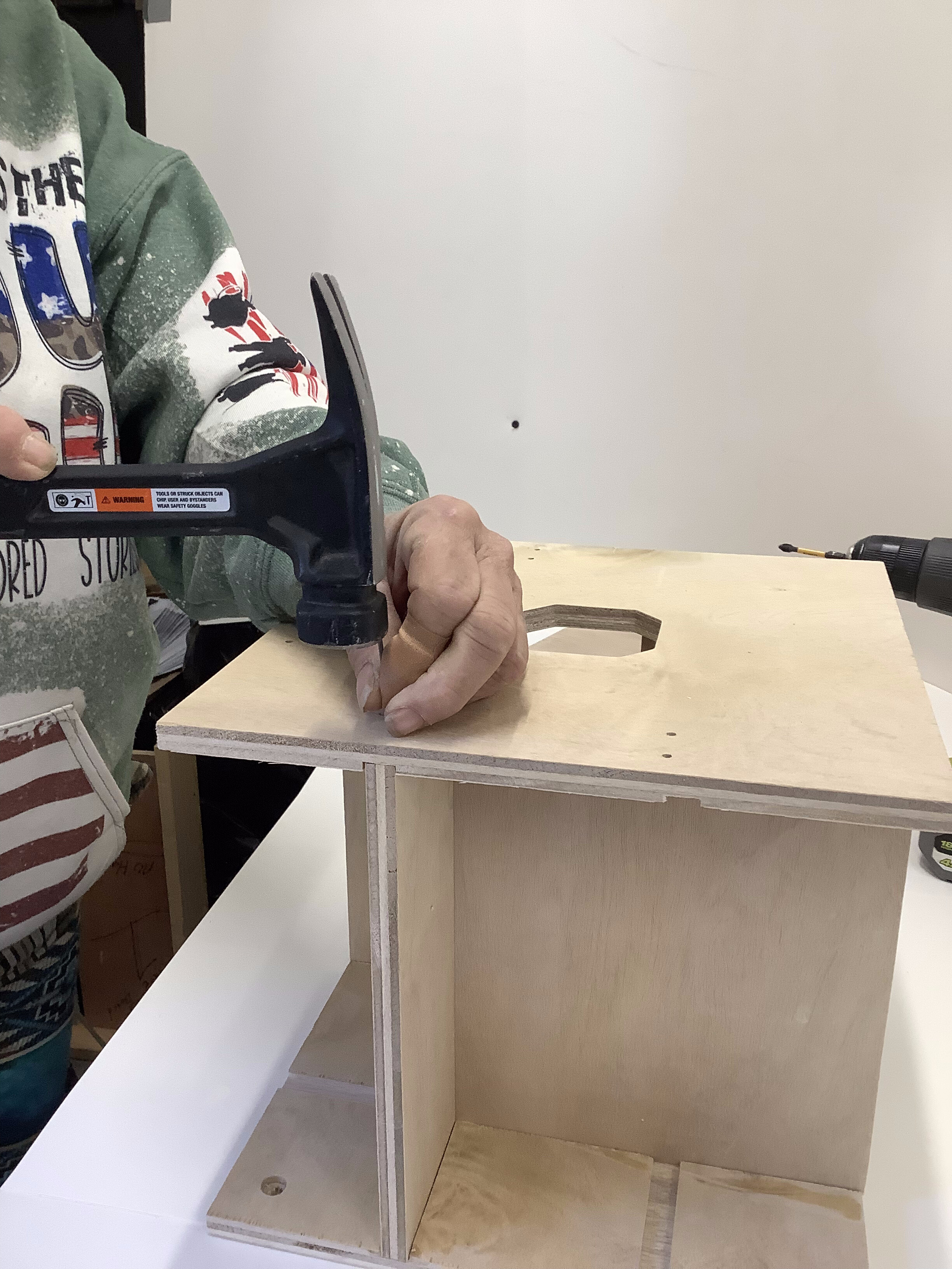 |
| Nail the Middle Plate into the 4 Inner Walls. Be sure not to nail near the edges! |
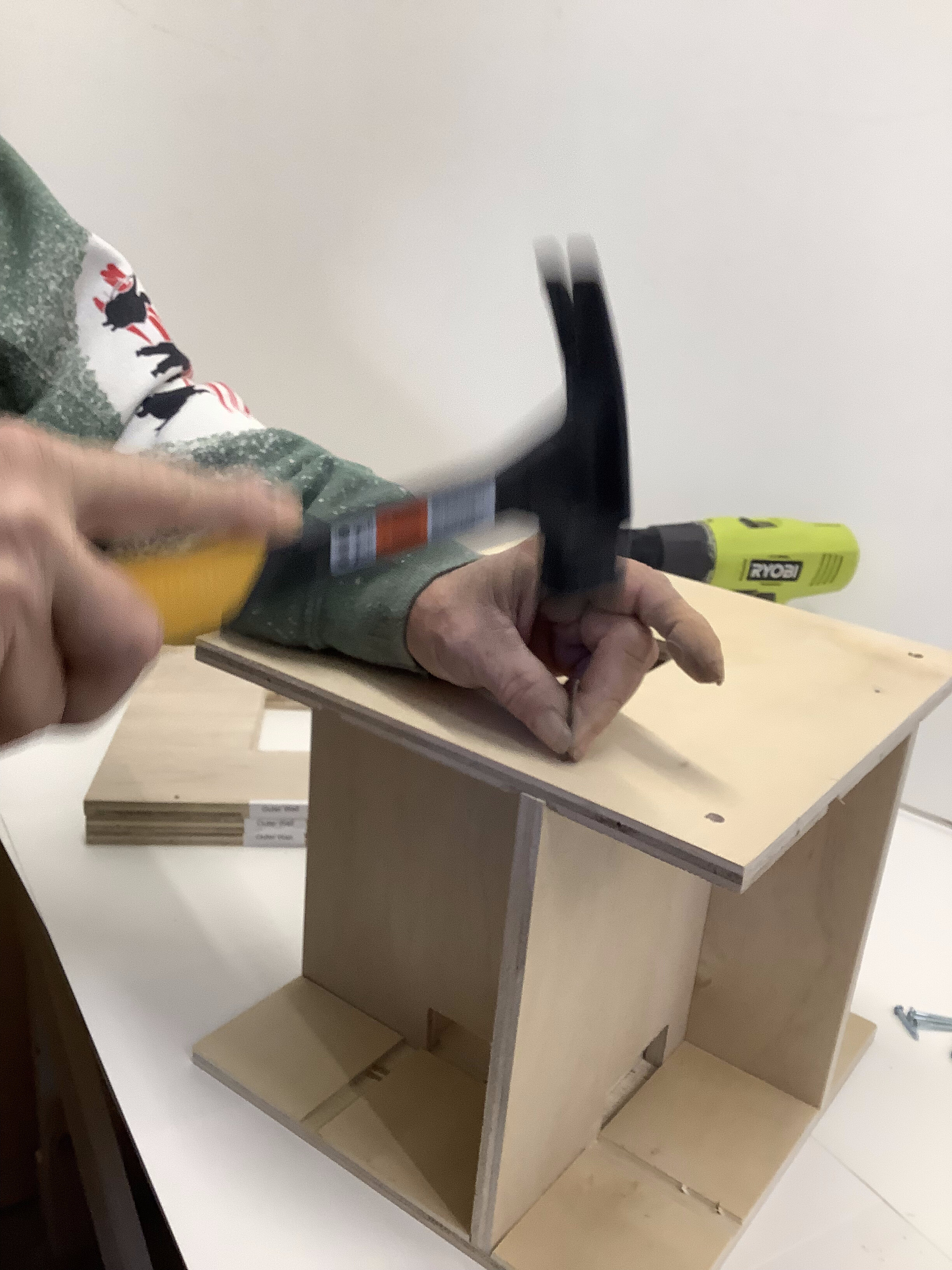 |
Flip the unit over and nail the Bottom Plate down to the 4 Inner Walls. |
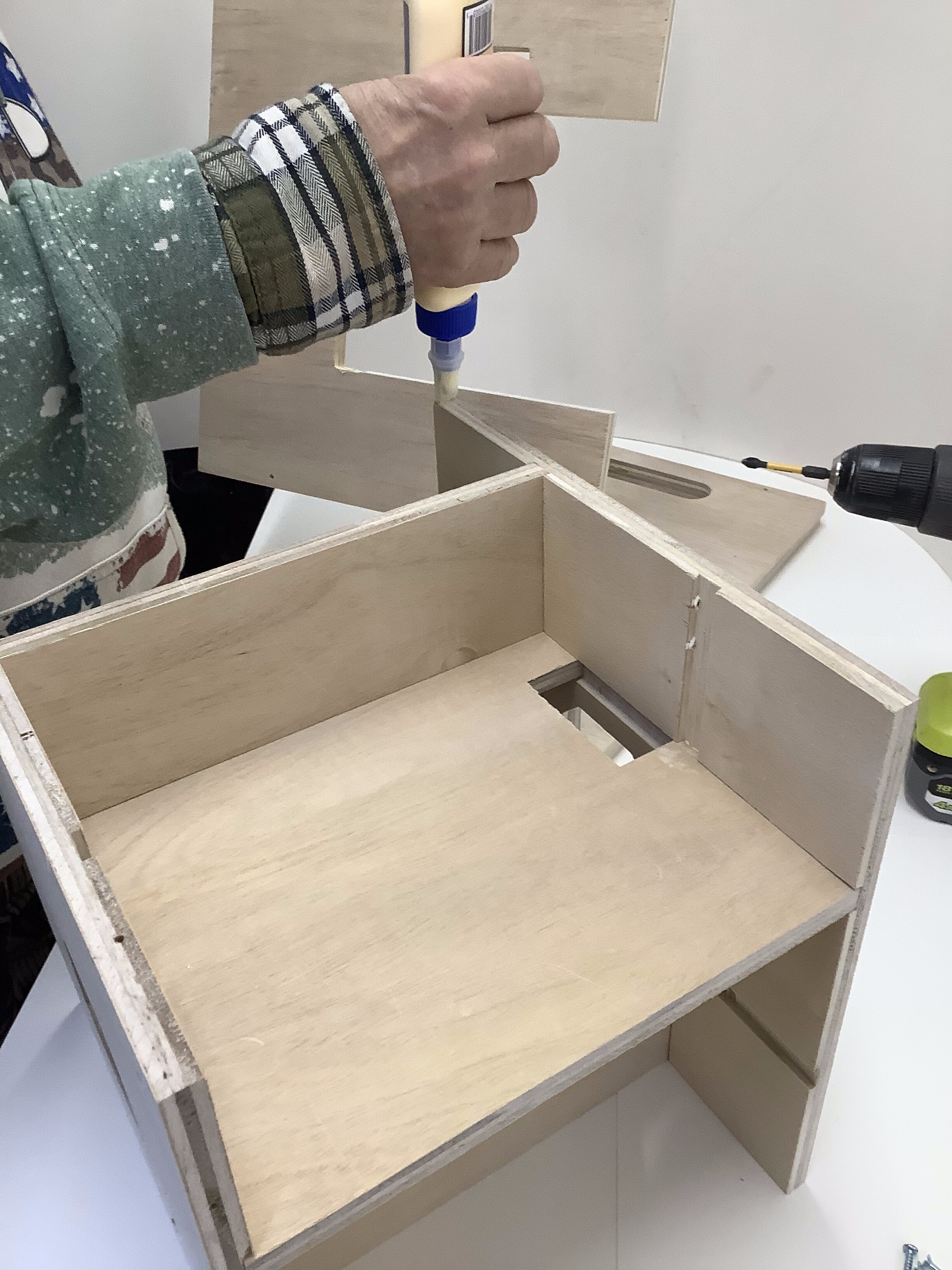 |
[[IMPORTANT - 1 edge of the Middle Plate does NOT have pilot holes. This is the FRONT.]]
Flip the unit on its side so the Bottom is towards you and the Front is to the RIGHT. |
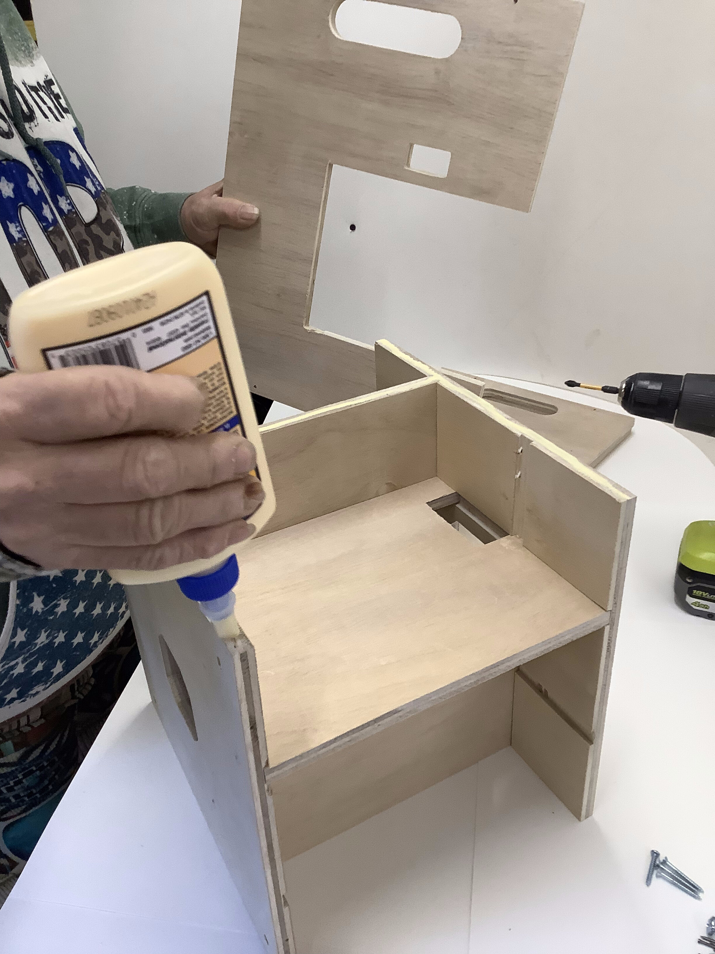 |
Apply glue to the edges the Outer Wall will rest on. This will be the left wall looking from the front. |
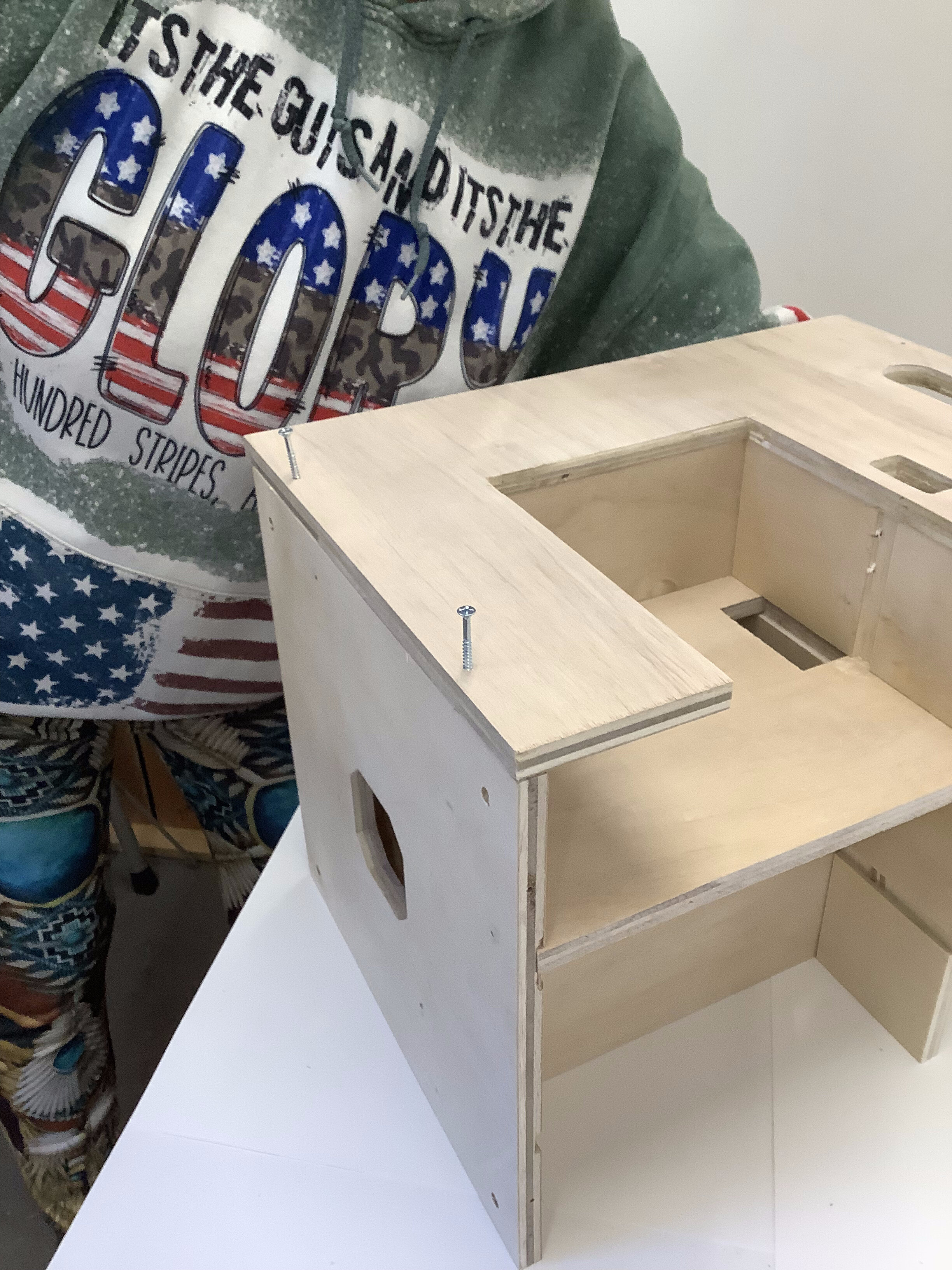 |
Place an Outer Wall on the unit. The bottom right corner should be flush with the front edge of the Bottom Plate and the holes should line up with the pilot holes. The bottom of the Middle Plate should line up with the top of the cut out and the inner wall should be flush with the back of the cut out.
Fasten in place with the screws and a few nails. |
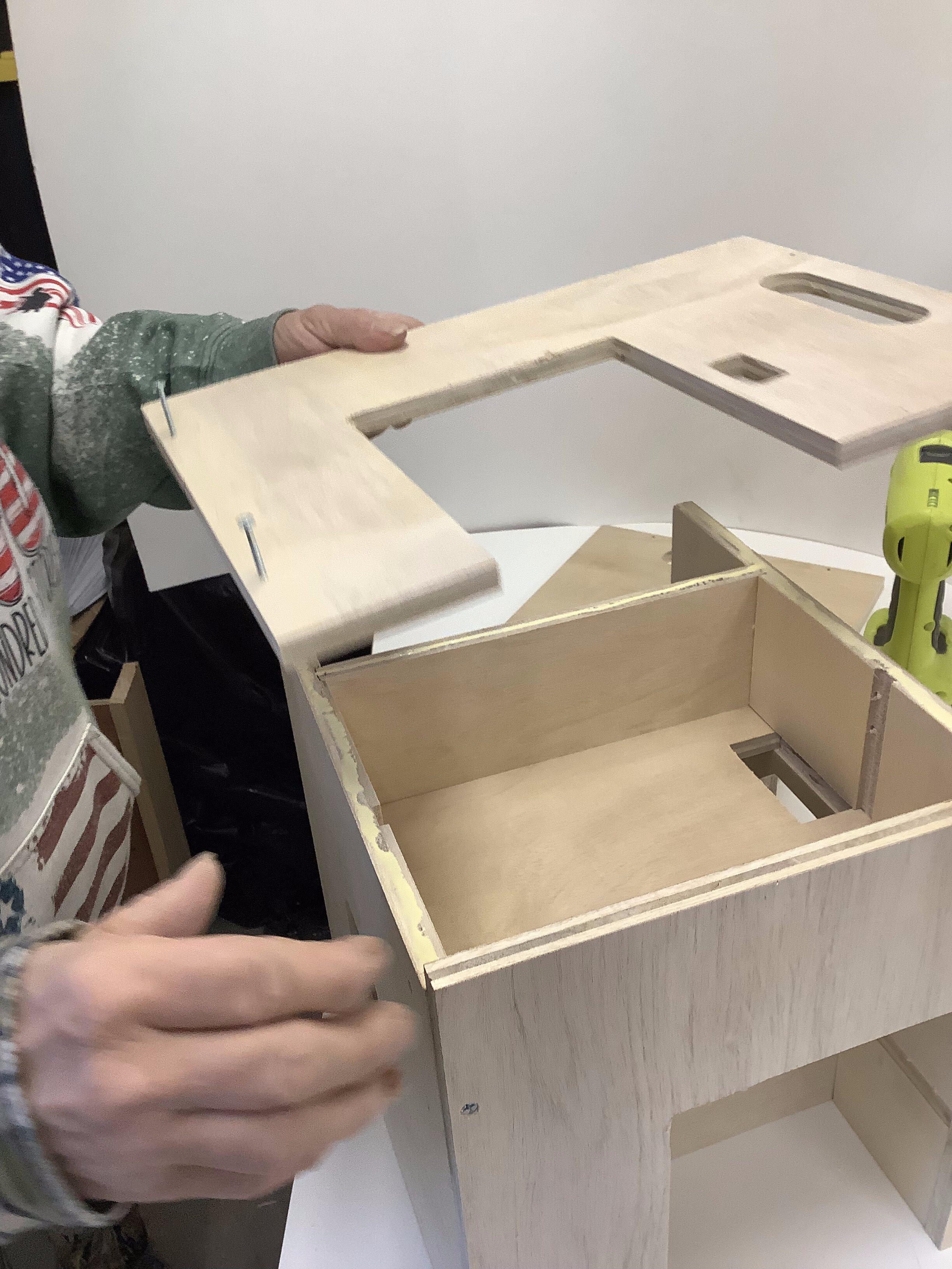 |
Rotate the unit 90° to the right, apply glue and place another Outer Wall. |
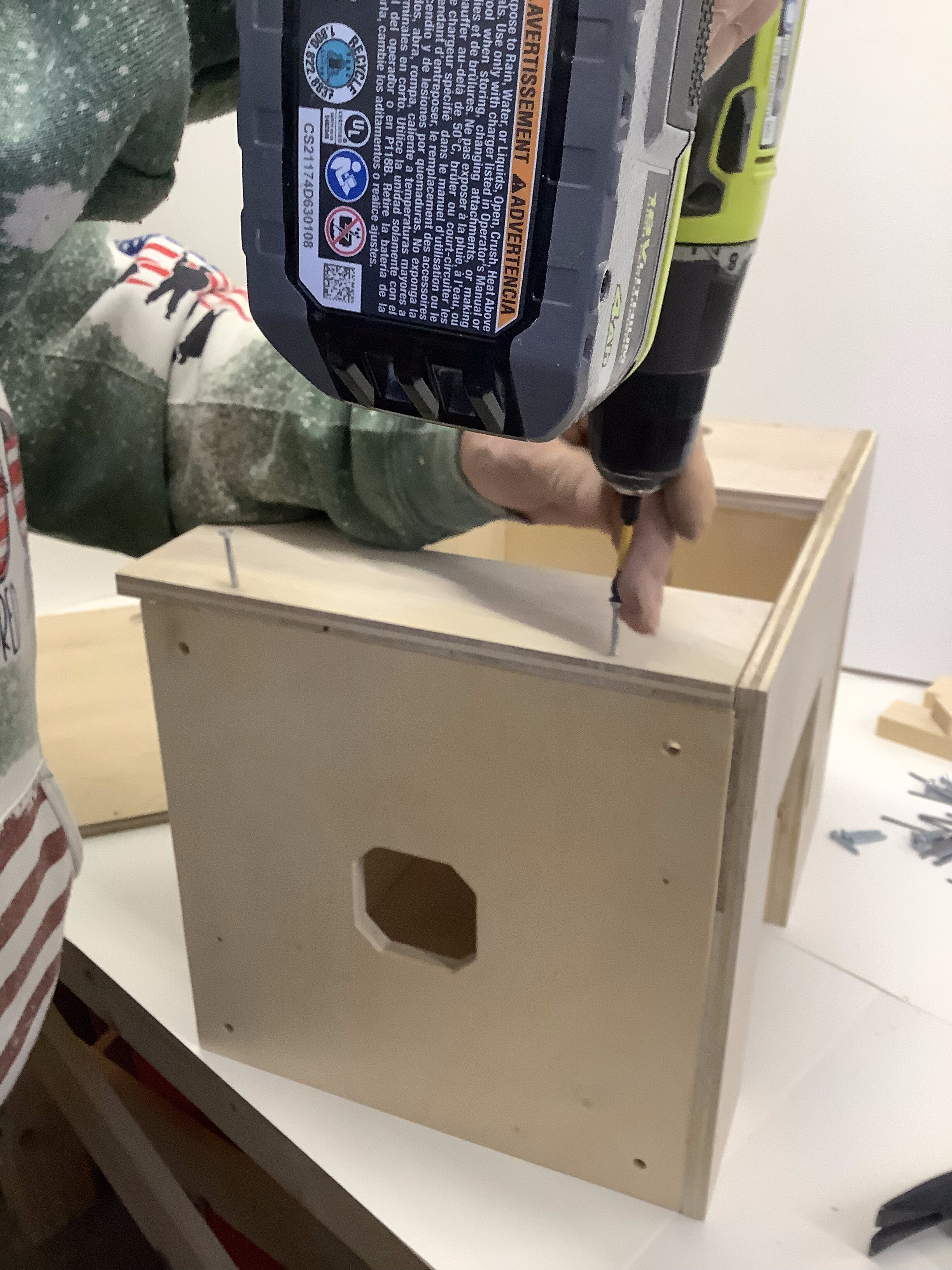 |
| Fasten with screws and a few nails. Repeat with the third Outer Wall. |
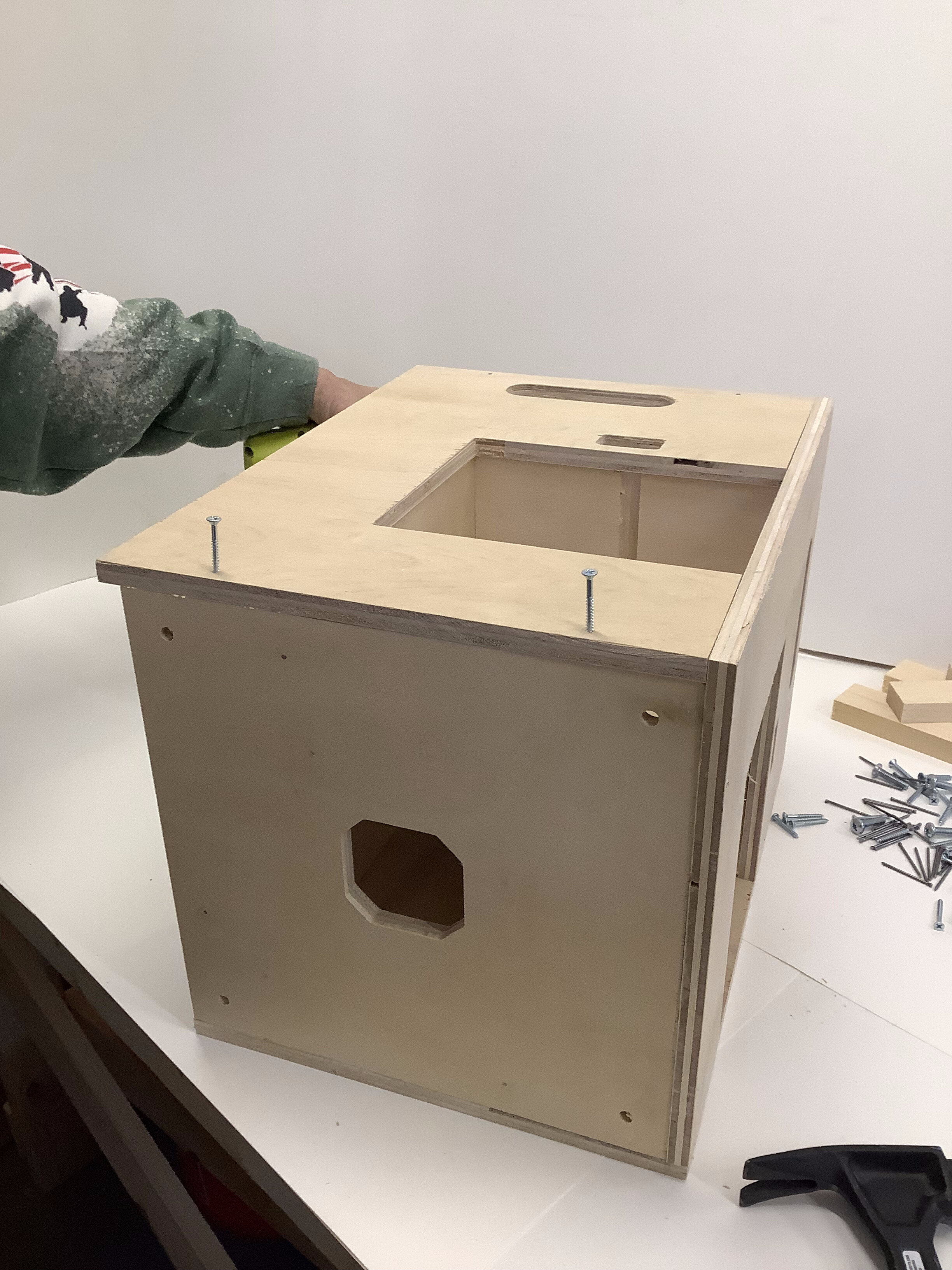 |
This picture shows how the edge of the Outer Walls extend beyond the Bottom plate. |
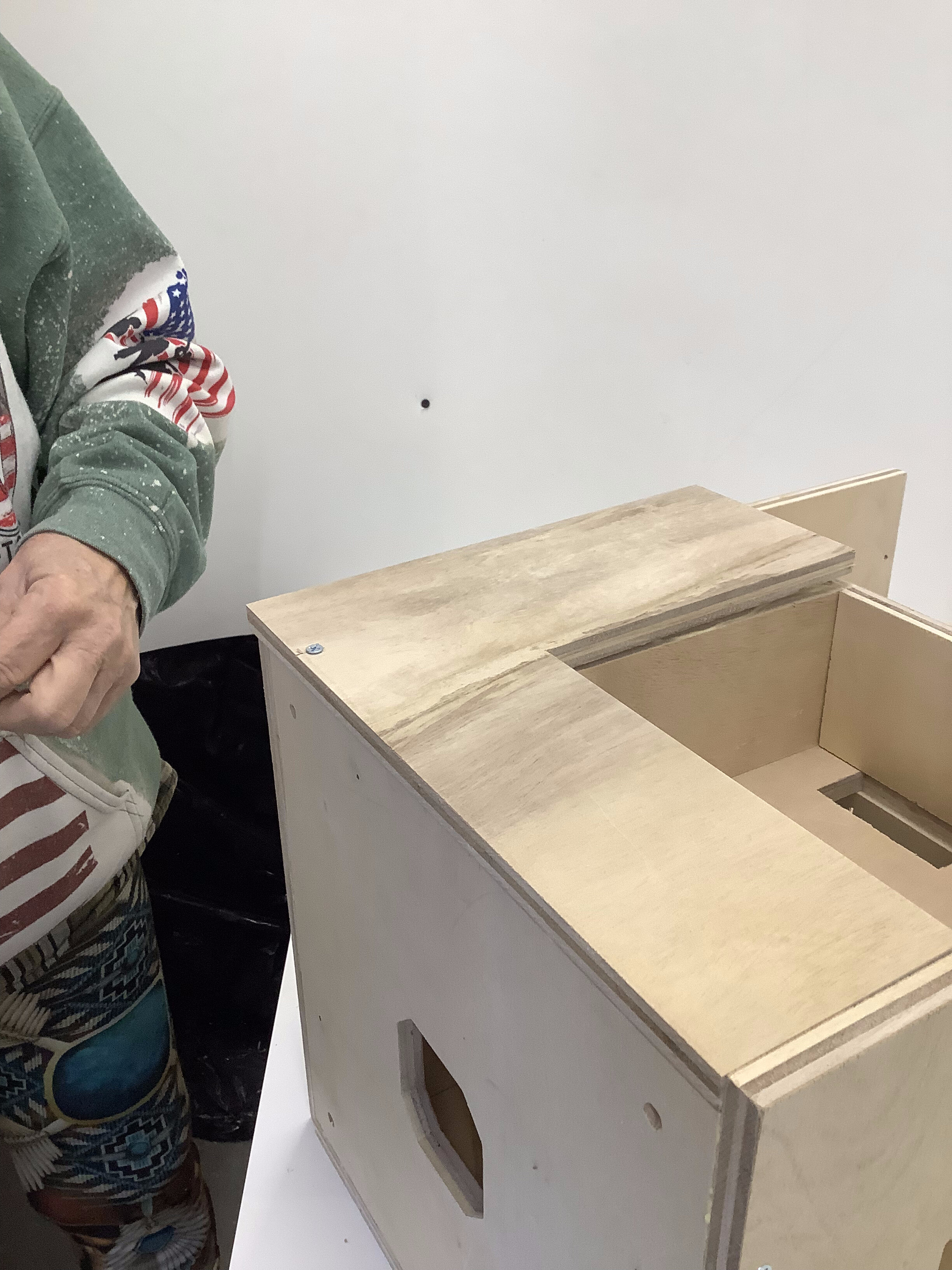 |
| Flip the unit 90° onto its back. This shows how the Short Wall is placed. Align it without glue to start. |
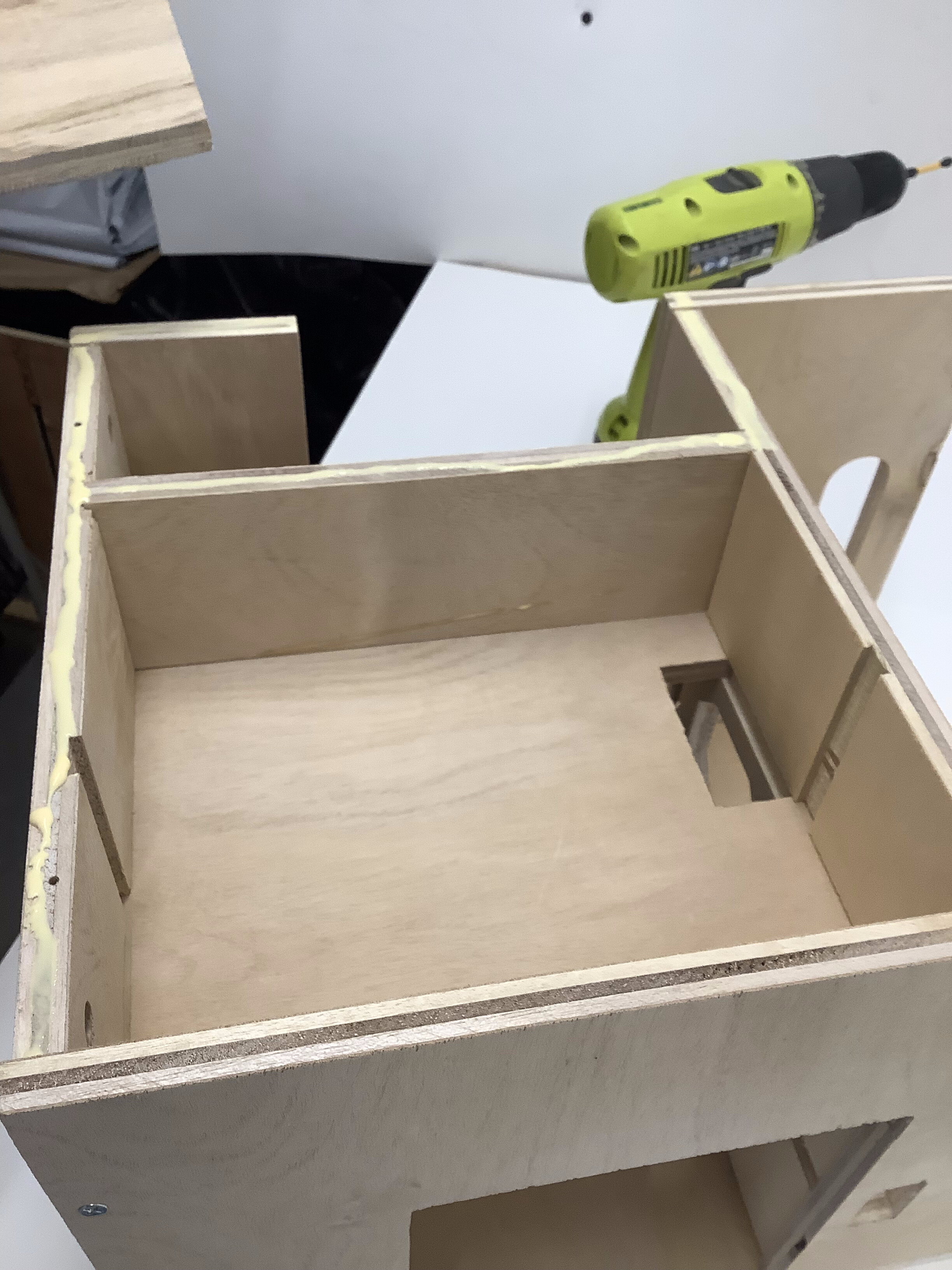 |
Add glue ONLY where the Short wall is supported by the unit. |
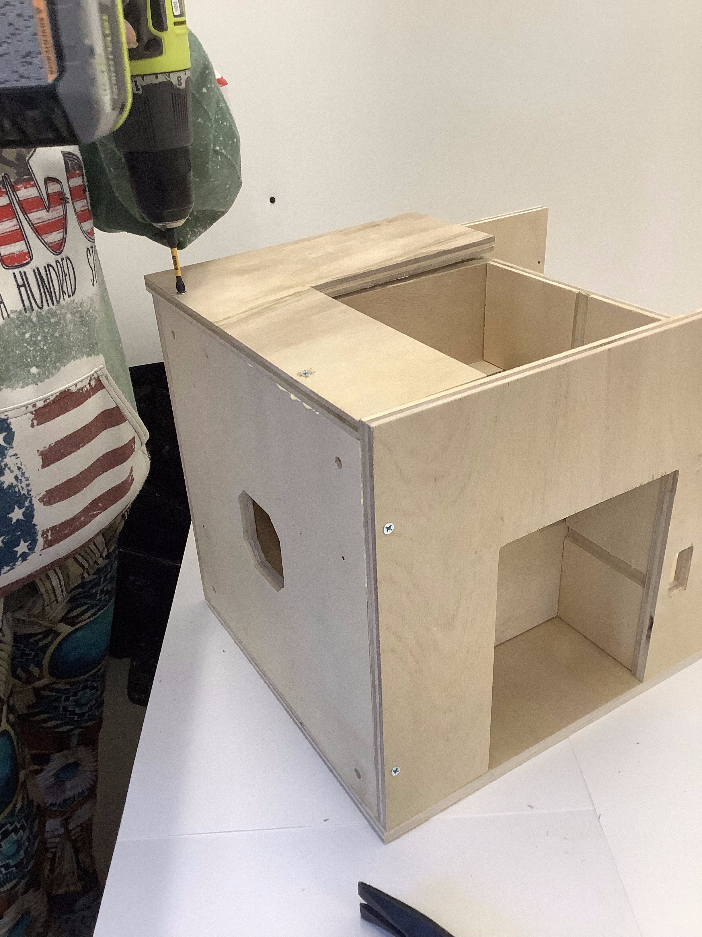 |
| Screw and nail the Short Wall into place. |
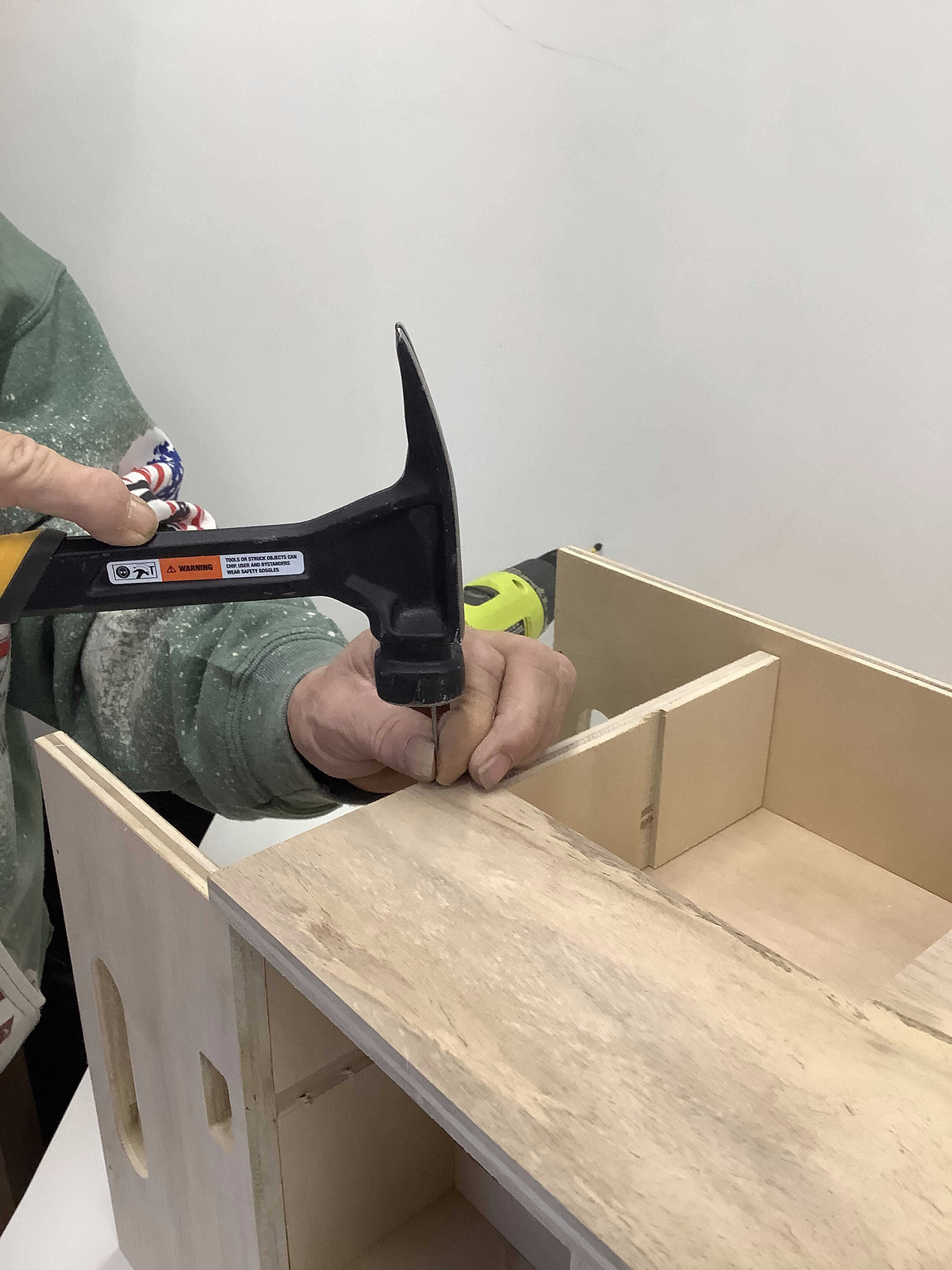 |
Notice where the outer corner of the Short wall meets the first Outer Wall you attached. |
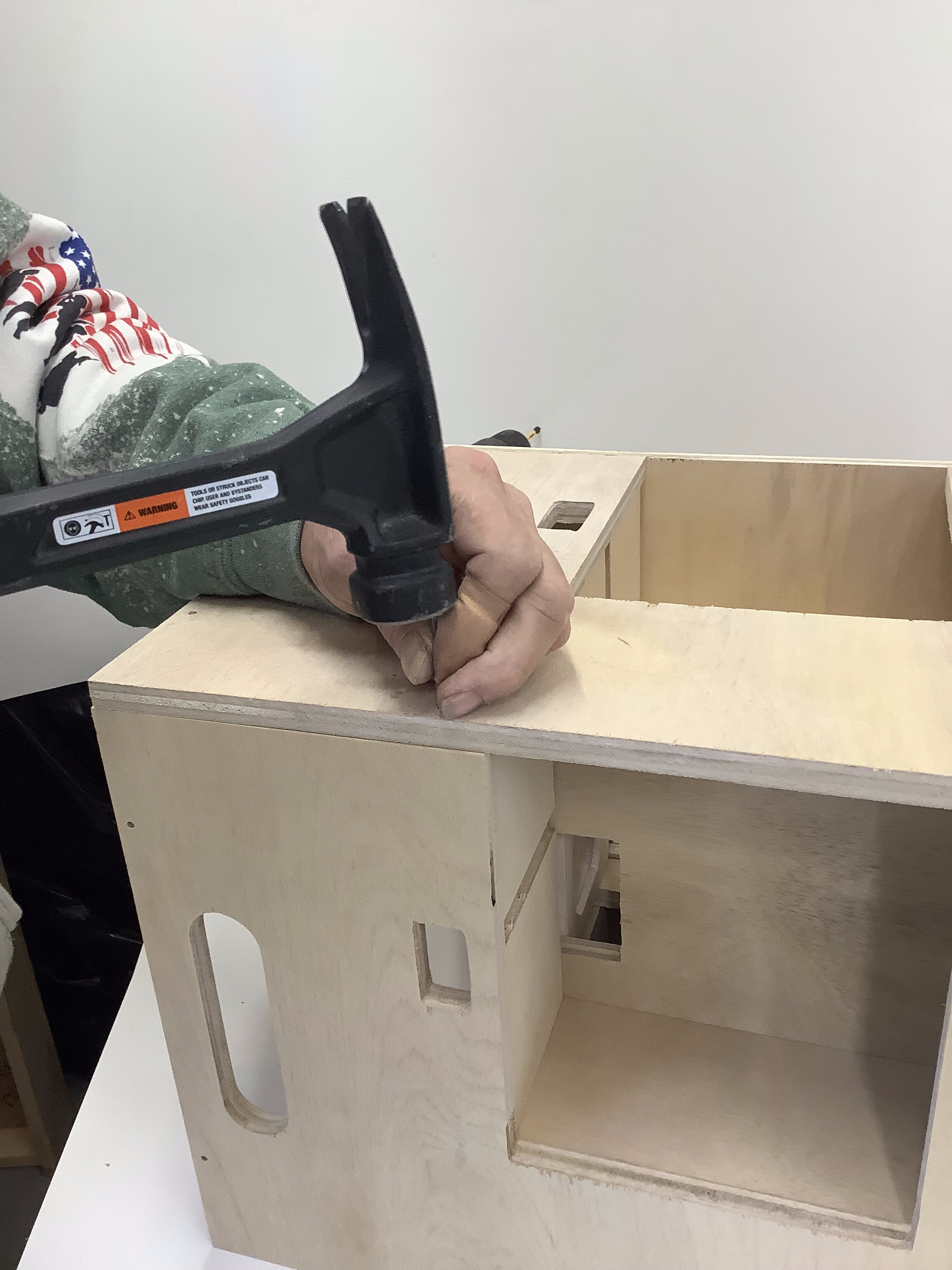 |
| Attach the Outer Walls to the adjoining Outer walls with nails. Stay away from the corners of the boards you are nailing into to prevent splitting. |
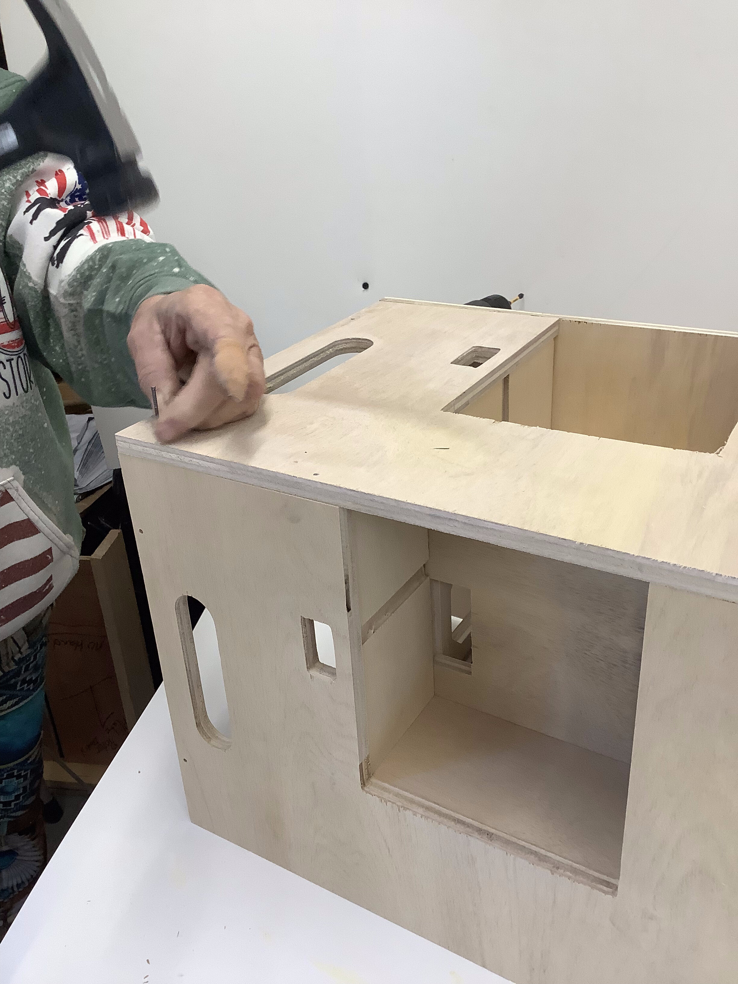 |
More nails! |
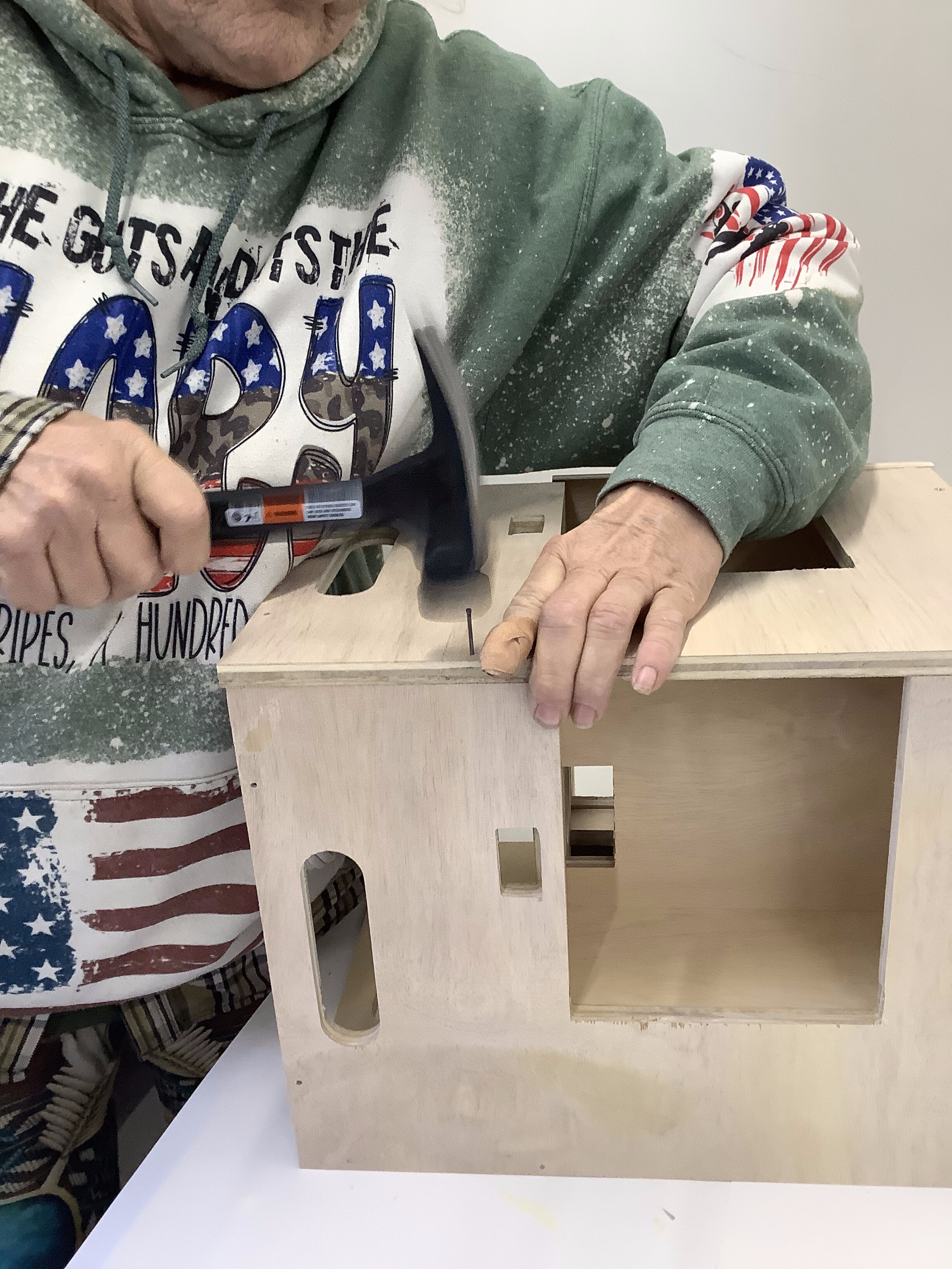 |
| More nails! |
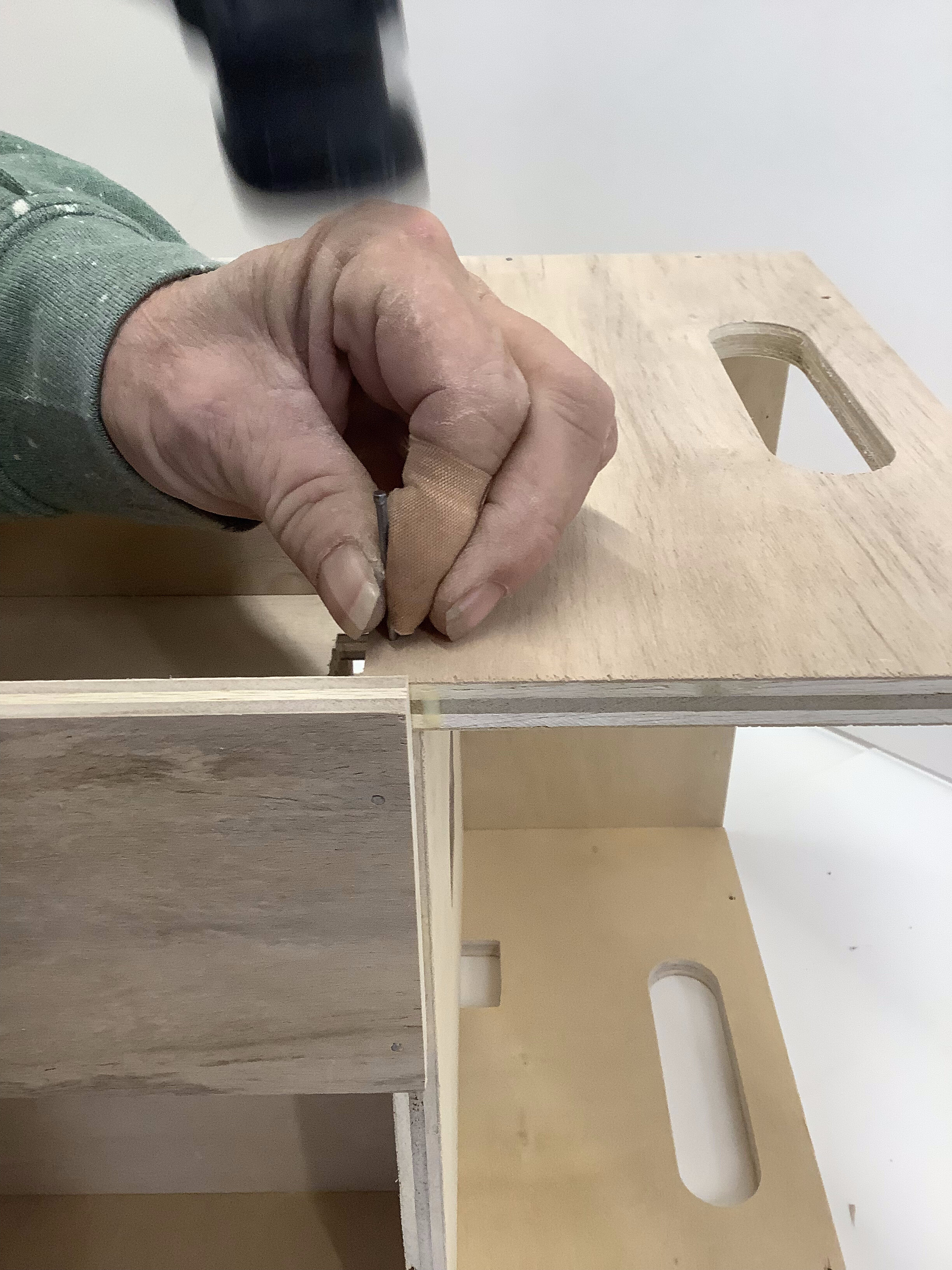 |
There should be nails along the top of the Outer Wall cutout into the Middle plate. |
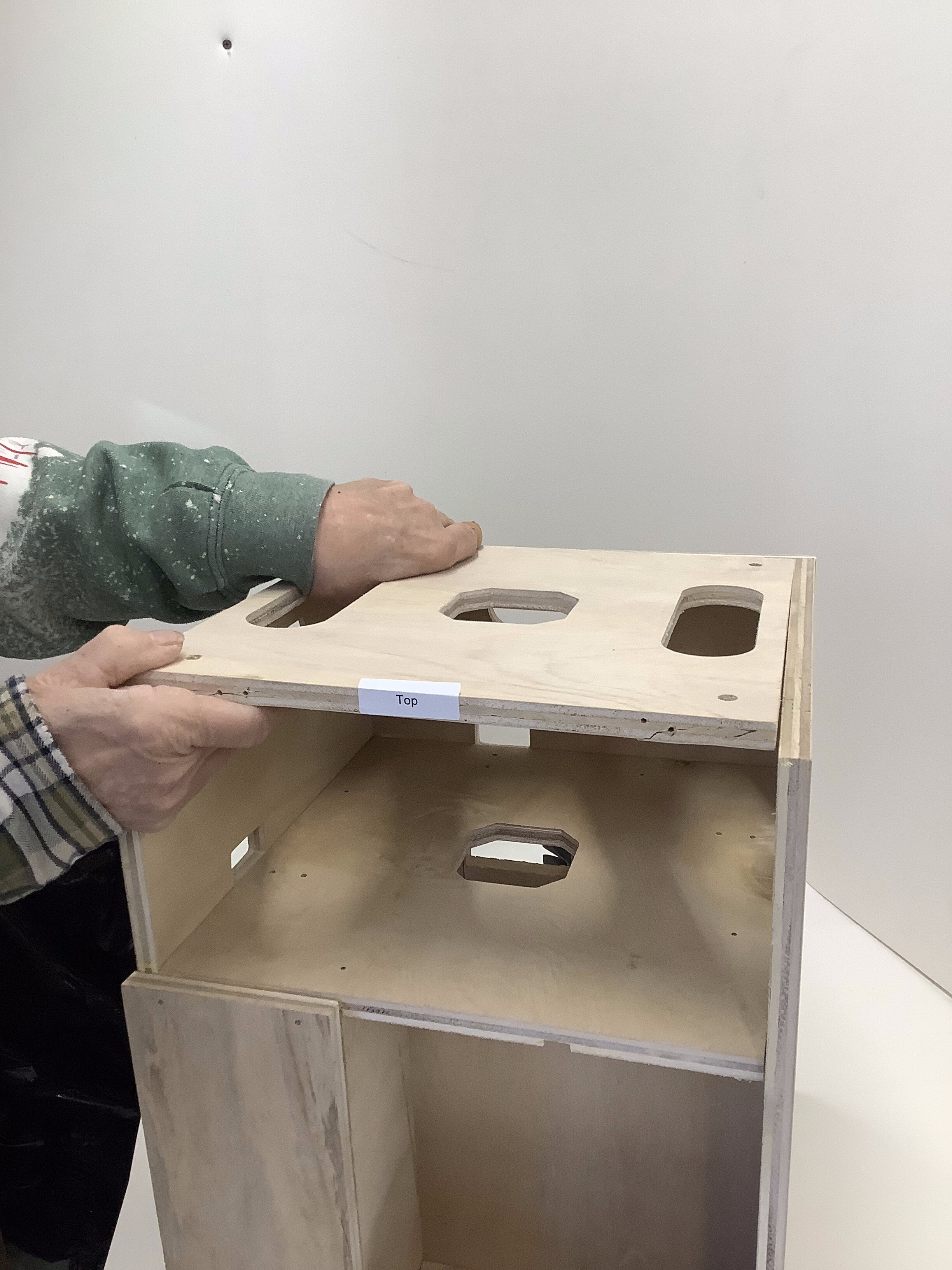 |
| This shows how the Top Plate fits, with the handle holes to the sides. Do not attach yet |
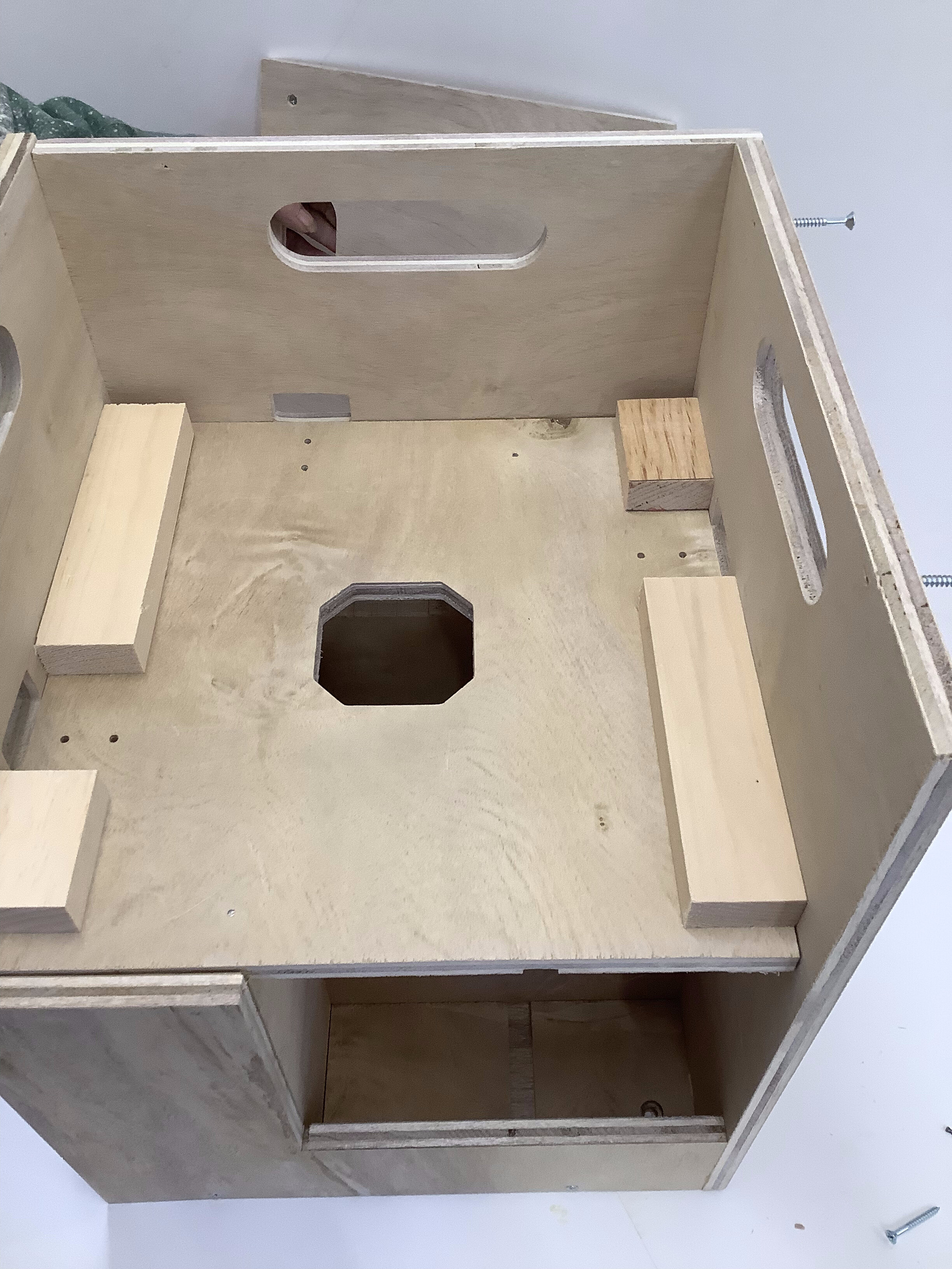 |
For the larger chargers, place the included spacer blocks as shown leaving enough room for the connectors to be screwed down. |
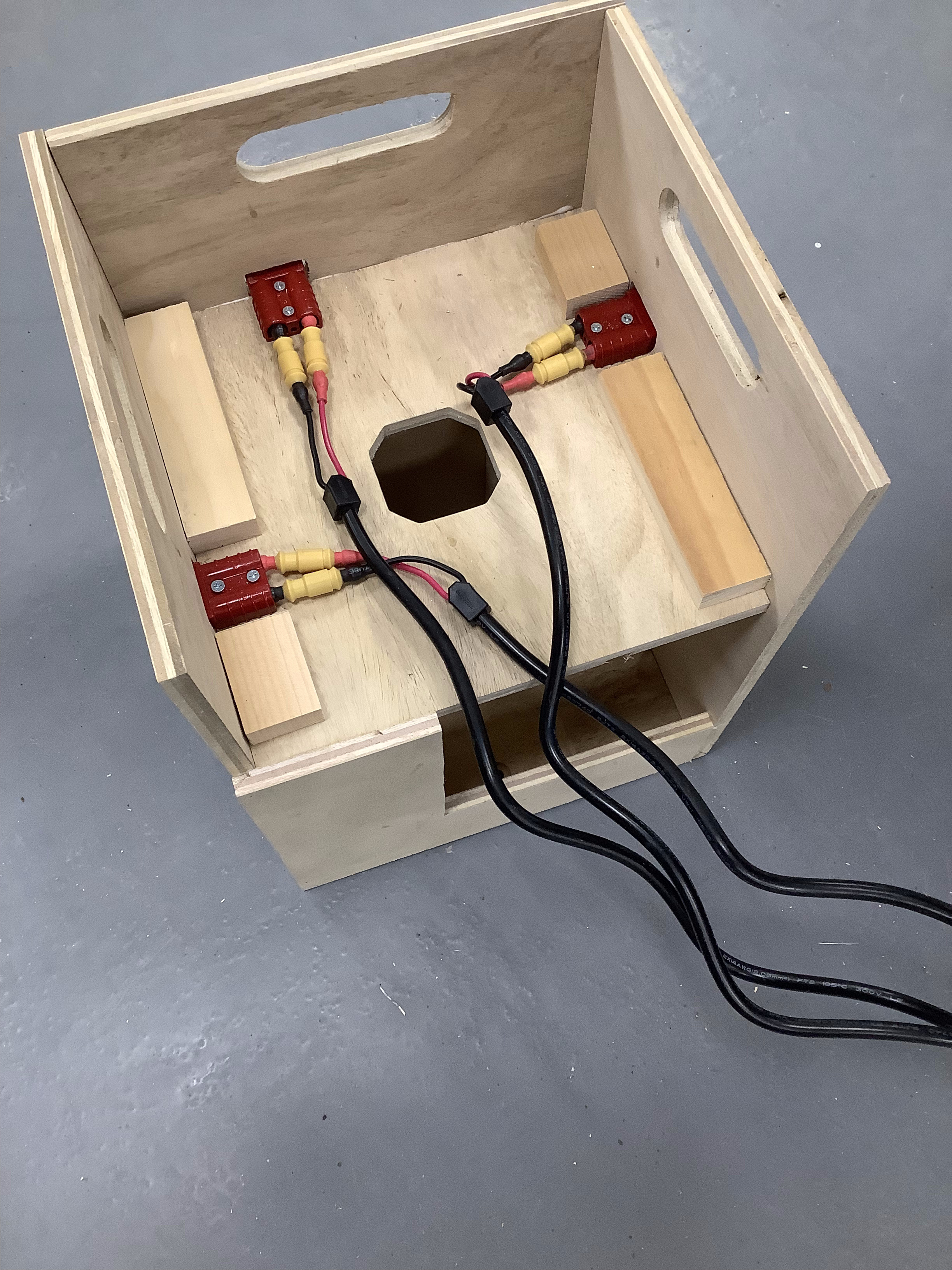 |
| This shows how the (Anderson) Battery Connectors are fastened to the Middle Plate. Use the #6 by 1" cap head screws. |
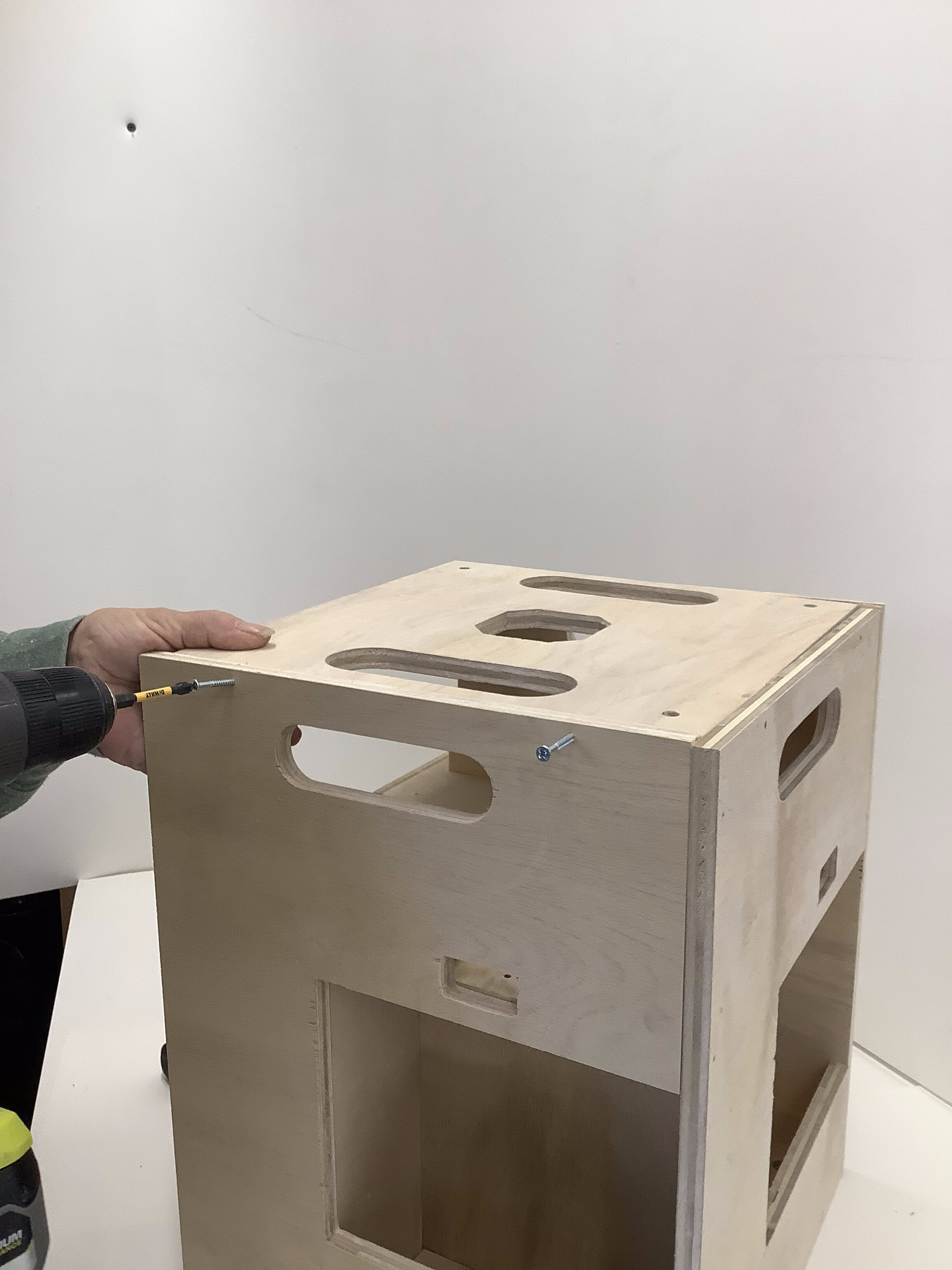 |
Do not attach the Top Plate until the Battery Charger is mounted and wired.
The Hole in the center may be used to pass the power cord down and out underneath the unit. |
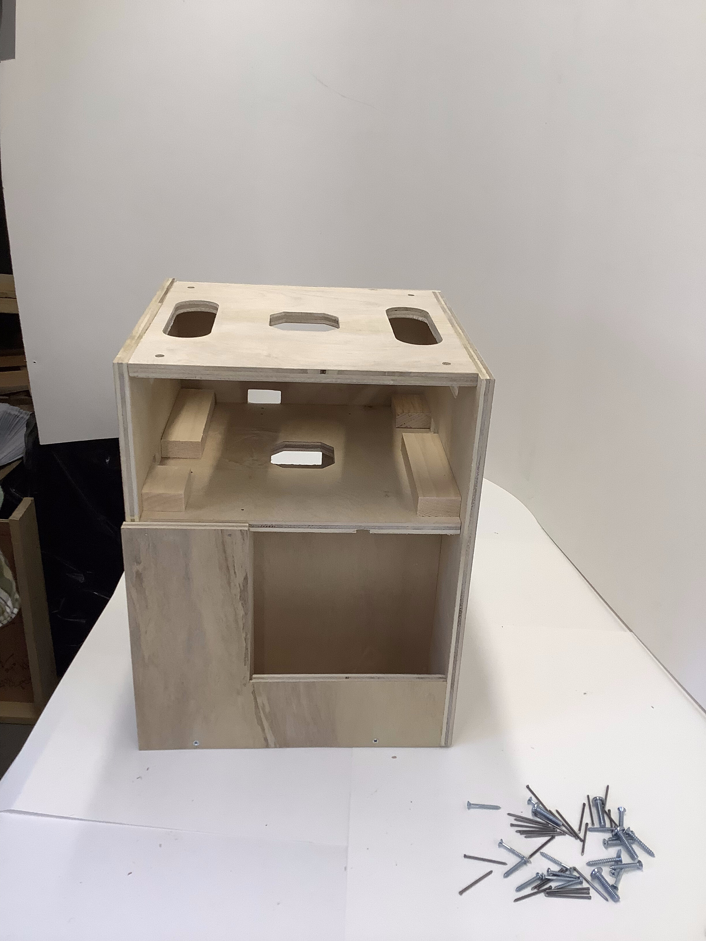 |
| The finished Battery Cart without a charger installed. |


